Radon Mitigation System Diagram: Labeled Parts and Required Clearances
By Cedar Rapids Radon Mitigation Research · Last verified: · Version 1.1
What are the key radon mitigation system statistics?
Each line stands alone: figure, year, qualifier, and named source. The clearest conflict in the verified sources is the vertical window clearance — see stat 1.
- 1ANSI/AARST SGM-SF-2023 §6.4.6(b) requires a radon exhaust to be at least 4 feet from an operable opening below it — double the 2-foot vertical relationship in EPA's 2025 Consumer's Guide to Radon Reduction, ANSI/AARST CCAH-2020-0523 §601.3, and the 2021 IRC Appendix AF §AF103.5.3.
- 2A radon exhaust must be at least 10 feet above the grade nearest the discharge under ANSI/AARST SGM-SF-2023 §6.4.5, ANSI/AARST CCAH-2020-0523 §601.2(2), and EPA's 2025 consumer guide. The 2021 IRC Appendix AF requires roof termination but does not state a 10-foot-above-grade minimum.
- 3Clearance from a wall that rises above the roof is 4 feet under ANSI/AARST SGM-SF-2023 §6.4.10(d), 10 feet under ANSI/AARST CCAH-2020-0523 §601.2(3), and 5 feet under Pennsylvania's 25 Pa. Code §240.308(b)(5).
- 4ANSI/AARST SGM-SF-2023 states exhaust placement as geometry: a 45-degree directional spread must not encounter an opening, building material, or occupied breathing space within 10 feet, and an 11-degree straight-line trajectory must remain clear for 20 feet (§6.4.3 and §6.4.4).
- 5ANSI/AARST SGM-SF-2023 sets a minimum vent-pipe capacity equal to a 3-inch inside-diameter pipe, raises the minimum to 4 inches where pressure-field analysis indicates more than 80 cubic feet per minute, and permits 2-inch pipe only where analysis verifies 40 cfm or less (§6.3.1 through §6.3.3).
- 6ANSI/AARST SGM-SF-2023 §6.1.1 requires a suction pit to contain a cleared void of at least 0.25 cubic feet — approximately 2 US gallons of excavated material — unless excavation is impracticable.
- 7Iowa's rewritten radon mitigation rule took effect July 1, 2026 and requires credentialed mitigators to follow the applicable ANSI/AARST mitigation standards as amended through August 1, 2025, naming SGM-SF-2023 for existing homes and SGM-MFLB-2023 for multifamily, school, commercial, and mixed-use buildings — Iowa Administrative Code 641—44.3(3)"c."
- 8The Iowa rule in force before July 1, 2026 instead required EPA's Radon Mitigation Standards (EPA 402-R-93-078, October 1993, revised April 1994) and ASTM E2121, and converted every “should” in those documents into a “shall.” That clause is absent from the current chapter.
- 9Iowa Administrative Code 641—44.10(3), effective July 1, 2026, exempts passive-system installers from credentialing, while 641—44.1(1) requires a credentialed specialist for passive-to-active conversion and modification of an existing active system.
- 10Iowa's 2026 rule defines a passive mitigation system as a vertical vent pipe routed through conditioned space from the suction pit to 12 inches above the roof, relying solely on convective airflow and using no in-line fan — 641—44.2.
- 11A credentialed Iowa mitigator must install a system that reduces radon below 4 pCi/L in the area or level where it is installed — 641—44.3(4)"e" — and accepting compensation for a system that fails to do so is an enforcement ground under 641—44.7(21).
- 12EPA's 2025 consumer guide lists typical radon reduction of 50 to 99 percent for active sub-slab suction and 30 to 70 percent for passive sub-slab suction. These are published technique ranges, not predictions for an individual house.
- 13ANSI/AARST SGM-SF-2023 §6.5.2 prohibits the fan in conditioned or occupiable space and directly beneath such space, including a basement, crawl space, or enclosed garage beneath living space; EPA's 2025 guide states the same principle in consumer language.
- 14Every fan-equipped system needs two monitoring functions under ANSI/AARST SGM-SF-2023: a continuously viewable operating-range indication and an active failure alert that is audible, vividly visible, or electronic (§8.2.1 through §8.2.3). The functions need not be two separate physical devices.
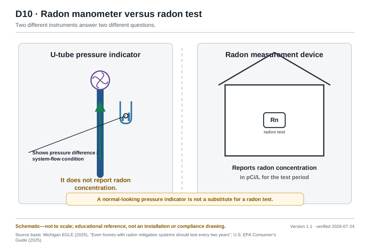
- 15The manometer on a radon pipe does not measure radon concentration. Michigan EGLE's January 29, 2025 guidance explains that it indicates pressure or airflow condition; only a radon test measures the concentration in the building.
- 16EPA's 2025 guide recommends starting a post-mitigation radon test no sooner than 24 hours after the system is operating and within 30 days of installation. Iowa's 2026 rule uses the same window when the building owner has not waived the state testing requirements before mitigation begins — 641—44.3(4)"d."
- 17Iowa HHS identified 11 jurisdictions with radon-resistant new-construction requirements before the 2026 state legislation, including Linn County, Bremer, Johnson, and Polk counties, and the cities of Altoona, Bondurant, Carroll, Iowa City, North Liberty, Norwalk, and Pella.
What is on this page?
Key statistics · How parts connect · Component reference table · Exhaust clearances · What the clearance table shows · Methodology · Diagrams by foundation type · Active vs passive · Manometer vs radon test · Which standard governs · Iowa's 2026 rules · What a diagram cannot prove · Limitations · Excluded claims · Dataset download · How to cite · FAQ · Sources · Change log
What does a radon mitigation system diagram show, and how does the system work?
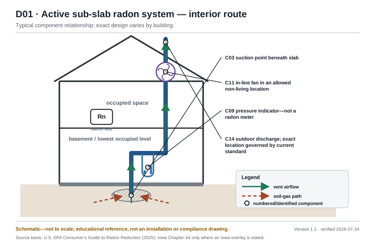
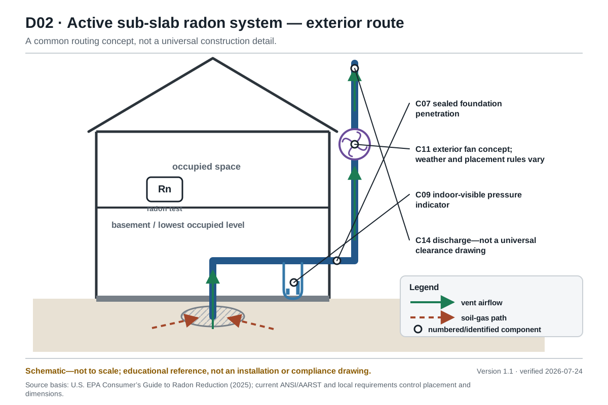
A radon mitigation system lowers the air pressure in the soil under a building so soil gas moves into a pipe instead of into the house. A collection point below the slab, below a crawl space membrane, or inside a drain-tile loop connects to a vent pipe; in an active system, an in-line fan pulls on that pipe continuously and discharges the gas outdoors above the roof. EPA describes active sub-slab suction — also called sub-slab depressurization — as the most common and usually the most reliable method for homes with a basement or slab-on-grade foundation.
The physics is a pressure difference. Indoor air pressure is normally slightly lower than the pressure in the soil around a foundation, so the building draws soil gas in through cracks, joints, and openings. A mitigation system reverses that relationship under the slab. It is not a filter and it does not neutralize anything; it intercepts and redirects.
The path, in order
- Collection. Soil gas gathers in a permeable zone — crushed rock under a slab, the space under a sealed crawl space membrane, a perforated drain-tile loop, or the void network inside a hollow block wall.
- Suction point. A pipe penetrates the slab or membrane into that zone. Under the slab, material is excavated to create a void so the pipe draws from a pocket rather than pressing against dirt.
- Vent pipe. Rigid pipe carries the gas upward, sloped back toward the suction point so condensation drains down rather than pooling.
- Fan. In an active system, an in-line fan sits on a vertical run, outside conditioned space.
- Exhaust. The pipe discharges outdoors, above the roof, away from anything that could draw the gas back in.
- Monitoring. A viewable operating-range monitor shows whether the fan-equipped system remains within its established range. An active notification function warns when the fan or another mechanical component fails.
- Verification. A radon test — not the gauge — establishes whether indoor concentration actually dropped.
Reading the labels on any radon diagram
Diagrams vary, but the vocabulary is consistent. Suction point and suction pit are the opening and the excavated void beneath it. Soil-gas retarder is the sheeting over crawl space soil. Riser is the vertical run of pipe. Manometer is the U-shaped fluid gauge. Termination or discharge point is where the pipe ends outdoors. Sub-slab depressurization and soil suction describe the same family of methods.
What are the parts of a radon mitigation system, and what governs each one?
This reference tracks 22 components that can appear in a residential radon mitigation diagram. Nearly every one carries a published requirement — a minimum size, spacing, prohibited location, or required label. The table pairs each component with the governing provision without turning the data into an installation sequence.
★ Directly checked in a current issuer publication or the standards publisher's official technical bulletin reproducing the current clause. ● Directly checked in the official 2021 IRC model-code publication; local applicability depends on adoption and amendment.
Table 1. Radon mitigation system component reference
| # | Component | What it does | Governing requirement | Authority and section | Tier |
|---|---|---|---|---|---|
| 1 | Suction pit | The excavated void that lets the pipe draw from a pocket, not packed fill | Cleared void of at least 0.25 cubic feet (about 2 US gallons of excavated material) unless excavation is impracticable | SGM-SF-2023 §6.1.1 | ★ |
| 2 | Suction point seal | Stops indoor air short-circuiting into the pit | Permanent airtight seal; caulk meeting ASTM C920 Class 25 or better; gaps wider than ½ in pre-filled with backer rod | SGM-SF-2023 §6.1.1.1, §7.2.1–7.2.2 | ★ |
| 3 | Sealed sump lid | Turns an open sump into a collection point instead of an entry route | Rigid rot-resistant lid, mechanically fastened, gasket or non-permanent caulk, all penetrations sealed; removable access port at least 4 in across where a pump is present | SGM-SF-2023 §7.5.1, §7.5.1.1 | ★ |
| 4 | Drain-tile connection | Uses the footing drain loop as the collection plenum | Must not compromise the drainage system's capacity to move water | SGM-SF-2023 §6.1.1.2 | ★ |
| 5 | Soil-gas retarder (crawl space) | The sealed surface that makes sub-membrane suction possible | At least 6-mil nominal thickness; seams sealed for sub-membrane systems; non-sealed seams lapped at least 12 in; tears patched with at least 6 in of overlap; mechanically fastened to walls and footings; perimeter sealed | SGM-SF-2023 §7.6, §7.6.3, §7.6.4, §7.7.1–7.7.4 | ★ |
| 6 | Soil-gas retarder (new construction) | Same function, built in | At least 6-mil polyethylene, or 3-mil cross-laminated, lapped at least 12 in and extended to all foundation walls | IRC 2021 Appendix AF §AF103.3 | ● |
| 7 | Gas-permeable layer (new construction) | The sub-slab plenum installed before the pour | Uniform layer of clean aggregate at least 4 in thick | IRC 2021 Appendix AF §AF103.2 | ● |
| 8 | Vent pipe — diameter | Carries soil gas from plenum to exhaust | At least the cross-sectional area of 3-in inside diameter pipe; at least 4-in where pressure-field analysis indicates more than 80 cfm for the whole system; 2-in permitted only where analysis verifies 40 cfm or less | SGM-SF-2023 §6.3.1–6.3.3 | ★ |
| 9 | Vent pipe — diameter (new construction) | Same | At least 3-in diameter gas-tight ABS or PVC, same diameter throughout, from the permeable layer through the roof | IRC 2021 Appendix AF §AF103.5.3 | ● |
| 10 | Vent pipe — material | Durability and joint integrity | Schedule 40 PVC (ASTM D2665, F891, or F1488) or ABS (ASTM D2661, F628, F1488), solvent-welded per manufacturer instructions; exterior gutter downspout permitted only on the fan's pressure side, at 3×4 in minimum for 3-in equivalence or 4×5 in for 4-in | SGM-SF-2023 §6.2.5, §6.3.7 | ★ |
| 11 | Vent pipe — slope | Drains condensate and rain back to soil instead of blocking airflow | Continuous downward slope toward the suction point of at least ⅛ in per foot | SGM-SF-2023 §6.2.2 | ★ |
| 12 | Vent pipe — supports | Resists wind, ice, and sag over decades | No more than 10 ft apart on vertical runs, 4 ft on horizontal runs; no fastening by driving a screw through the pipe; existing plumbing and ductwork may not be used as support | SGM-SF-2023 §6.2.7.1–6.2.7.2 | ★ |
| 13 | Vent pipe — insulation | Prevents ice blockage and condensation damage | R-4 or better where freezing is likely to cause ice buildup that degrades performance; R-1.8 or better with an external vapor barrier where surface condensation would damage building materials | SGM-SF-2023 §6.2.9 | ★ |
| 14 | Pipe labels | Keeps a future trade from cutting the wrong pipe | At least one label at each floor level and in attics, garages, and crawl spaces; label titles in lettering at least ¼ in tall, additional text at least ⅛ in, in contrasting color | SGM-SF-2023 §8.4.4, §8.4.1 | ★ |
| 15 | Fan | Creates the negative pressure field | Continuous-duty rated; sealed against water and soil-gas leakage; allows water to pass through or around it when running; thermal overload protection; mounted on a vertical run; joined with flexible couplings meeting ASTM D5926 or C1173 | SGM-SF-2023 §6.5.1, §6.5.4 | ★ |
| 16 | Fan location | Keeps the fan and positive-pressure piping out of occupied space | Prohibited in conditioned or occupiable space and directly beneath it, including a basement, crawl space, or enclosed garage under living space; permitted in attics, on exteriors, or in garages not beneath occupiable space; not below ground except in a protected, drained exterior location | SGM-SF-2023 §6.5.2–6.5.3, §6.5.4(e) | ★ |
| 17 | Electrical disconnect | Allows safe shutdown for service | A means of disconnect in line of sight and within 6 ft of the fan; outdoor wiring in conduit unless local code permits otherwise and not a plug connection; no wiring run inside the duct | SGM-SF-2023 §8.3.1, §8.3.3–8.3.4 | ★ |
| 18 | Disconnect label | Stops someone switching the system off by accident | Must identify the disconnect as a system component — e.g., 'Radon Fan – Do Not Turn Off' | SGM-SF-2023 §8.4.5 | ★ |
| 19 | Viewable operating-range monitor | Shows whether a fan-equipped system remains within its established operating range | Required on a fan-equipped system unless the remote-monitoring exception applies; must continuously display a measured value, be readily viewable and protected, and show the established operating range | SGM-SF-2023 §8.2.1 | ★ |
| 20 | Active notification monitor | Alerts the occupant when the fan or another mechanical component fails | Required in addition to the viewable operating-range function: clear audible tone, vividly visible light, or electronic notification; powered failure indication may not share the fan branch circuit unless it has an independent backup supply; automatic reset is required after power interruption | SGM-SF-2023 §8.2.2, §8.2.3(e)–(f) | ★ |
| 21 | System label / tag | The identity plate | Placed on a primary component; for owner-occupied homes carries the install date, how to read the monitor and what to do on failure, a retest recommendation of at least every two years, state and federal resources, and the installer's name, phone, and credential number | SGM-SF-2023 §8.4.2, §8.4.2.1 | ★ |
| 22 | Floor-drain trap | Blocks soil air entering through a drain | A trap holding at least 6 in of water, a one-way valve, or re-routing to a condensate pump or floor drain | SGM-SF-2023 §7.8.2 | ★ |
Source: ANSI/AARST current standards catalogue; AARST Consortium, February 2024 SGM technical bulletin reproducing the harmonized clauses required by reference to SGM-SF-2023; International Code Council, 2021 IRC Appendix AF. Requirements are paraphrased because standards text is copyrighted. Verified July 24, 2026.
What are the required clearances for a radon vent pipe?
Four current primary references address radon exhaust placement, and they do not all set the same numbers. SGM-SF-2023, CCAH-2020-0523, and EPA's 2025 guide require at least 10 feet above grade; the 2021 IRC Appendix AF requires roof termination but does not state that grade-height minimum.
The clearest conflict is the opening below the exhaust. EPA, CCAH, and the 2021 IRC use a 2-foot vertical relationship in their respective provisions, while SGM-SF-2023 requires 4 feet from operable openings below the discharge; Iowa's current Chapter 44 incorporates SGM-SF-2023 for applicable credentialed existing-home work.
Table 2. Radon exhaust and termination clearances, four authorities compared
| Requirement | ANSI/AARST SGM-SF-2023 ★ | ANSI/AARST CCAH-2020-0523 ★ | IRC 2021 Appendix AF ● | EPA Consumer's Guide 2025 ★ |
|---|---|---|---|---|
| Height above grade nearest the discharge | At least 10 ft — §6.4.5 | At least 10 ft — §601.2(2) | Not specified; the stack exits through the roof | At least 10 ft above the ground |
| Horizontal clearance from operable openings | At least 10 ft to the side — §6.4.6(a) | At least 10 ft in any direction from air intakes including windows and doors, excluding attic vents — §601.3 | At least 10 ft from any window or opening into conditioned space that is less than 2 ft below the exhaust — §AF103.5.3 | At least 10 ft from windows, doors, and other openings, unless the exhaust vents at least 2 ft above them |
| ⚠ Key conflictVertical separation where opening sits below the exhaust | At least 4 ft from operable openings below the discharge — §6.4.6(b) | 2 ft above the opening relieves the 10 ft requirement — §601.3 | 2 ft — §AF103.5.3 | 2 ft |
| Height above a pitched roof at the penetration | At least 1 ft at the point penetrated — §6.4.10(a) | At least 1 ft at the highest point of the penetration — §601.2(1) | At least 12 in above the roof — §AF103.5.3 | Above the surface of the roof |
| Height above roof edge (piping up the outside wall) | At least 6 in above the roof edge — §6.4.10(b) | Not addressed separately | Not addressed separately | Not specified |
| Height above a flat roof | At least 18 in — §6.4.10(c) | Not addressed | Not addressed | Not specified |
| Clearance from a vertical wall rising above the roof | At least 4 ft horizontally — §6.4.10(d) | At least 10 ft horizontally from a wall extending above the roof penetrated — §601.2(3) | Not addressed | Not specified |
| Clearance from mechanical air intakes (HRV, ERV, make-up air) | No separate small-system HRV/ERV distance in §§6.4.1–6.4.12; directional-spread, opening, people, and governing-code provisions apply. §6.4.13 increases distances for pipes larger than 4 in and refers pipes larger than 10 in to ASHRAE 62.1 Appendix B | At least 3 ft above or 10 ft away — §601.4 | Not addressed | Not specified |
| Discharge direction | Upward, within 45° of vertical; downward discharge prohibited — §6.4.9 | Outdoors, directed vertically upward — §601.1 | Through the roof — §AF103.5.3 | Above the roof surface |
| Plume geometry | A 45° spread from the discharge must not reach openings, building materials, or occupied breathing space within 10 ft; the 11° straight-line path must stay clear for 20 ft — §6.4.3, §6.4.4 | Not expressed geometrically | Not addressed | Not addressed |
| Terminating below the roof | Permitted only with justification recorded in the operations and maintenance plan, at least 20 ft above grade, at least 4 ft from operable openings above it, plus confirmatory testing in the adjoining occupiable area — §6.4.11 | Not addressed | Not addressed | Not addressed |
| 90-degree horizontal discharge | Permitted but discouraged; at least 20 ft above grade if it passes the roof edge — §6.4.12.1 | Not addressed | Not addressed | Not addressed |
| Diffused horizontal discharge or rain cap | At least 15 ft above grade, and at least 4 ft above or 15 ft away from operable openings — §6.4.12.2 | Not addressed | Not addressed | Not addressed |
| Animal screen at the terminus | Not specified; any airflow restriction must be accounted for in sizing — §6.3.5 | Mesh dimension at least 0.5 in — §601.1 | Not addressed | Not specified |
| How distance is measured | Shortest distance between nearest points, as if a string were stretched between them — §6.4.1.1 | For the mechanical air-intake separation in §601.4, measured around intervening obstacles | Not specified | Not specified |
Source: AARST Consortium's February 2024 SGM technical bulletin, SGM-SF-2023 §§6.4.1–6.4.13; ANSI/AARST CCAH-2020-0523 §§601.1–601.4 in the official publisher viewer; International Code Council, 2021 IRC Appendix AF §AF103.5.3; EPA, 2025 Consumer's Guide to Radon Reduction. Verified July 24, 2026.
States can be stricter, and a few write their own numbers. Pennsylvania is the clearest example we read: 25 Pa. Code §240.308 requires a termination point at least 5 feet horizontally from a vertical wall extending above the roof — neither the 4 feet in SGM-SF-2023 nor the 10 feet in CCAH-2020-0523 — and specifies that the 10-foot distance may be measured directly or with a flexible tape following the shortest path around solid objects, and that a chimney does not count as an opening into conditioned space. This is not a fifty-state survey.
The rule that governs is the one your jurisdiction adopted. SGM-SF-2023 states that where its requirements exceed local, state, or federal requirements, its requirements are the ones to follow (§2.3), and separately that adherence to the standard does not guarantee compliance with any authority's codes (§1.2.4). The jurisdiction having authority controls.
What does the clearance comparison show — and what does it not show?
Table 2 shows that four current primary references specify different relationships for the same physical component, and it shows exactly where each value comes from. That is a documentation finding, not a field survey of installed systems and not a judgment that one source is universally controlling.
Some of the divergence is structural rather than substantive. EPA's consumer guide is written for homeowners evaluating a contractor, not for designers; it compresses. The model code addresses new construction, where the stack is designed into the building and routed through the roof by default, so several retrofit-specific dimensions never arise. SGM-SF-2023 covers retrofits on buildings that already exist in every awkward configuration, which is why it carries the below-roof exception, the horizontal-discharge cases, and the plume-geometry rules the others don't need.
But the 2-foot versus 4-foot difference is substantive. It applies to the same situation — an exhaust point above an openable window — and the numbers differ by a factor of two. A writer citing 2 feet can accurately identify EPA's 2025 guide, CCAH-2020-0523, or the 2021 IRC Appendix AF. A writer describing the standard incorporated into Iowa Chapter 44 for applicable credentialed existing-home work after July 1, 2026 needs the 4-foot figure and the SGM-SF-2023 §6.4.6(b) citation.
How was this radon mitigation system dataset compiled?
This dataset is an editorial synthesis of primary-source requirements, not a field measurement, performance study, or survey. Each published value is paired with its authority, section, applicability, verification tier, source URL, and July 24, 2026 verification date so the tables and downloads can be reproduced.
What was collected: Every published requirement for a component visible in a residential radon mitigation system diagram — collection, piping, fan location, electrical disconnects, monitoring, labeling, sealing, exhaust placement, foundation method, testing, and Iowa credentialing.
When it was collected: All source reading and re-verification was completed on July 24, 2026.
Sources checked directly: ANSI/AARST SGM-SF-2023 (via the February 2024 technical bulletin); ANSI/AARST CCAH-2020-0523 (Sections 501, 601, and 701 in the official viewer); 2021 IRC Appendix AF (official ICC publication); Iowa Administrative Code 641—Chapter 44 (both the pre-July 2026 and current versions as published PDFs); Iowa Acts Chapter 1124; Iowa Administrative Code 481—Chapter 301 dated July 8, 2026; EPA's 2025 consumer guide (agency PDF); 25 Pa. Code §240.308; Michigan EGLE's January 29, 2025 guidance; Iowa HHS Radon Resources.
Processing: Each requirement was paraphrased, assigned to the component or comparison it governs, and recorded with the exact section path. Where a source is silent, the table says “not addressed” or “not specified”; no value was carried from another authority to fill the gap.
Verification tiers: ★ means the value was directly checked in a current issuer publication or the standards publisher's official technical bulletin. ● means the value was directly checked in the official 2021 IRC model code; whether it governs a building depends on jurisdictional adoption and amendment.
What this is not: We did not test a system, inspect a building, measure airflow or radon, or estimate the number of compliant installations.
How does the diagram change by foundation type?
Foundation type determines the collection method, and the collection method is what actually differs between one radon diagram and the next. EPA groups the basement and slab-on-grade approaches into four soil-suction methods — sub-slab, drain-tile, sump-hole, and block-wall — and describes sub-membrane depressurization as the most effective approach for crawl space homes. Homes with more than one foundation type may need a combination.
Table 3. Collection method by foundation, with the constraint that governs the drawing
| Foundation or condition | Collection method | What the pipe connects to | Governing constraint worth knowing |
|---|---|---|---|
| Basement or slab-on-grade | Active sub-slab depressurization | An excavated pit below the slab | Often a single suction point is enough; the number depends on how easily air moves through the material under the slab and on the strength of the source (EPA) |
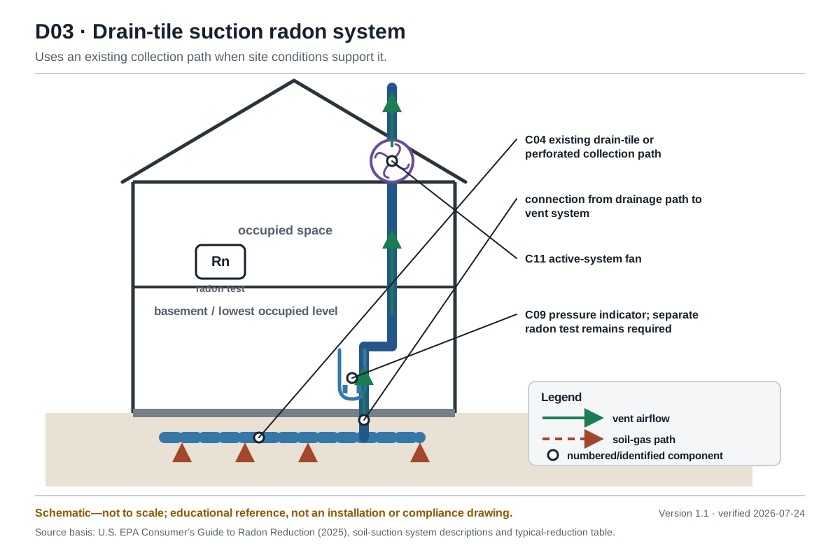
| Perimeter drain tile | Drain-tile suction | The existing perforated drainage loop | The connection must not reduce the drainage system's ability to move water (SGM-SF §6.1.1.2); EPA notes it can work with partial or complete loops |
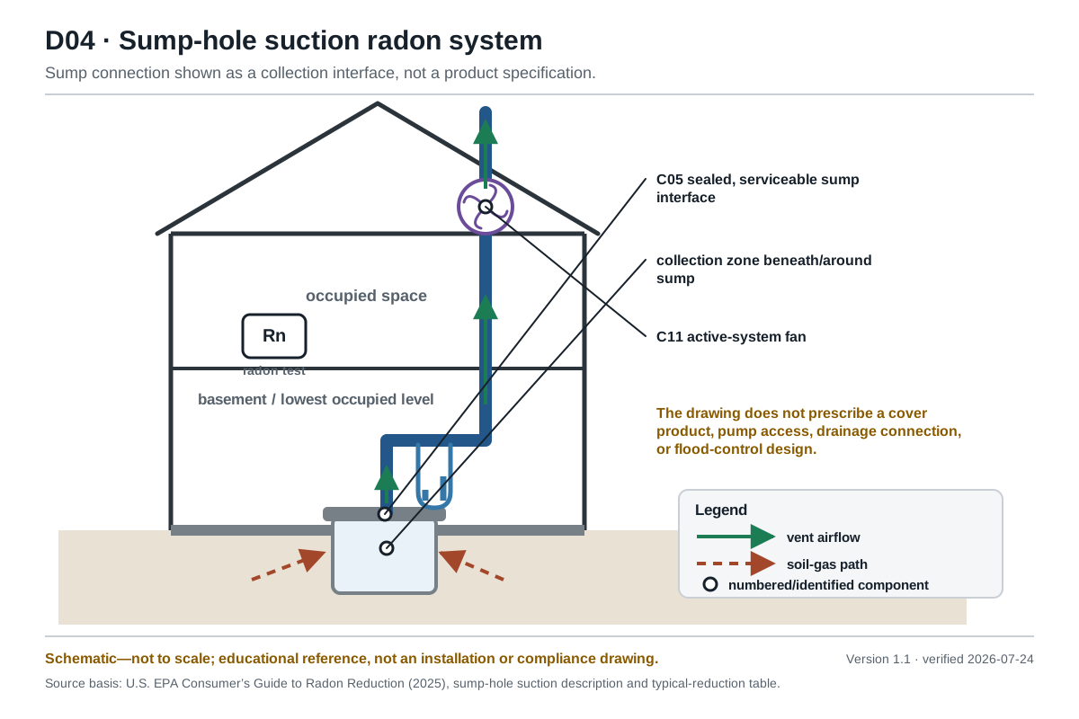
| Sump present | Sump-hole suction | The sealed sump pit | The lid must stay serviceable — a removable access port at least 4 in across is required where a pump is present (SGM-SF §7.5.1.1) |
| Crawl space | Sub-membrane depressurization | The sealed space under a soil-gas retarder | The entire perimeter of the plenum must be sealed or closed; where a section cannot be safely reached, only the accessible edges must be closed (SGM-SF §7.7.4) |
| Crawl space, inaccessible | Crawl space depressurization | The crawl space air itself | Permitted only where the area cannot be safely accessed or lacks working height (SGM-SF §6.1.4.2); EPA calls it the less favorable option and flags combustion backdrafting |
| Hollow block foundation wall | Block-wall depressurization | The void network inside the wall | All accessible openings and gaps surrounding the depressurized void network must be closed (SGM-SF §7.4.1); EPA notes it is often combined with sub-slab suction |
| Mixed foundations | Combination | More than one collection zone | EPA states directly that homes with more than one foundation type may require a combination of techniques |
Source: EPA, 2025 Consumer's Guide to Radon Reduction, “Radon Reduction Techniques”; ANSI/AARST SGM-SF-2023 clauses as cited. Verified July 24, 2026.
Foundation-system diagram set
Schematics, not to scale; they do not determine suction-point count, fan sizing, pressure-field extension, or code compliance. Verified July 24, 2026.
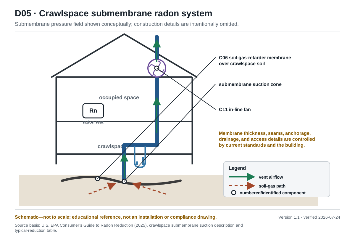
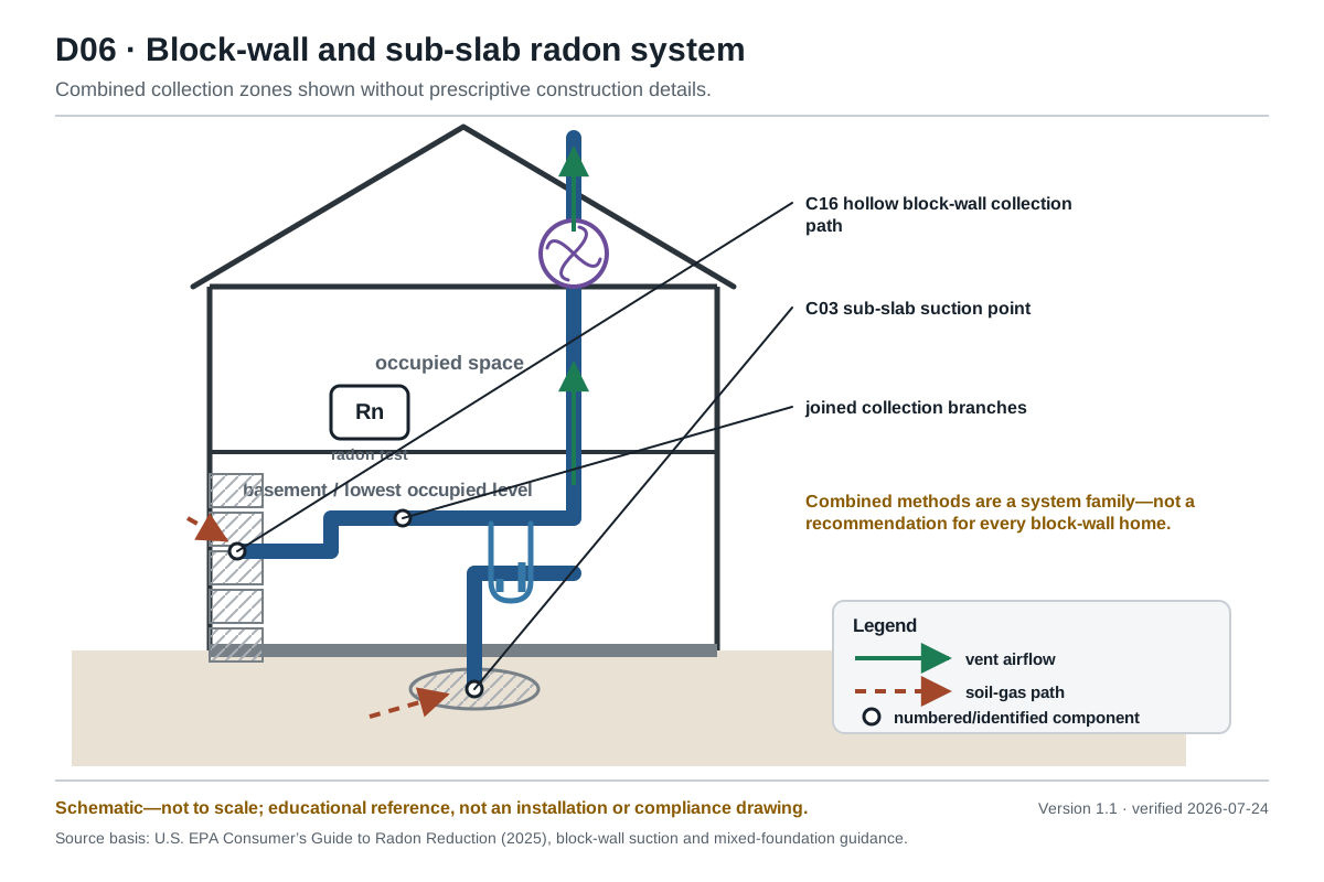
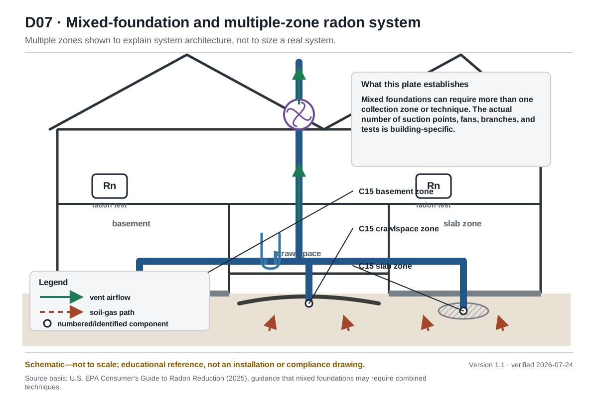
What EPA publishes for typical reduction by technique
These are published ranges for the method, taken from EPA's table. They describe what the technique has typically achieved, not what any particular installation will achieve.
Table 4. Typical radon reduction by mitigation technique
| Technique | Typical radon reduction | EPA's stated condition |
|---|---|---|
| Sub-slab suction (sub-slab depressurization) | 50 to 99 percent | Works best where air moves easily in the material under the slab |
| Passive sub-slab suction | 30 to 70 percent | May be more effective in cold climates; not as effective as active |
| Drain-tile suction | 50 to 99 percent | Works with either partial or complete drain tile loops |
| Sump-hole suction | 50 to 99 percent | Works best where air moves easily to the sump from under the slab |
| Block-wall suction | 50 to 99 percent | Hollow block walls only; requires sealing of major openings |
| Crawl space sub-membrane depressurization | 50 to 99 percent | Less heat loss than natural ventilation in cold winter climates |
| Crawl space natural ventilation | 0 to 50 percent | Costs variable |
| Basement pressurization | 50 to 99 percent | Works best with a tight basement isolated from outdoors and upper floors |
| Sealing of radon entry routes | See condition | Normally used only alongside other techniques |
| Natural ventilation | Variable, temporary | Significant loss of heated or cooled air |
Source: EPA, Consumer's Guide to Radon Reduction: How to Fix Your Home, 402/K-10/005 (2025 printing), “Radon Reduction of Various Mitigation Techniques.” Verified July 24, 2026.
What is the difference between an active and a passive radon system?
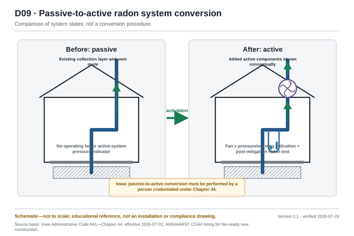
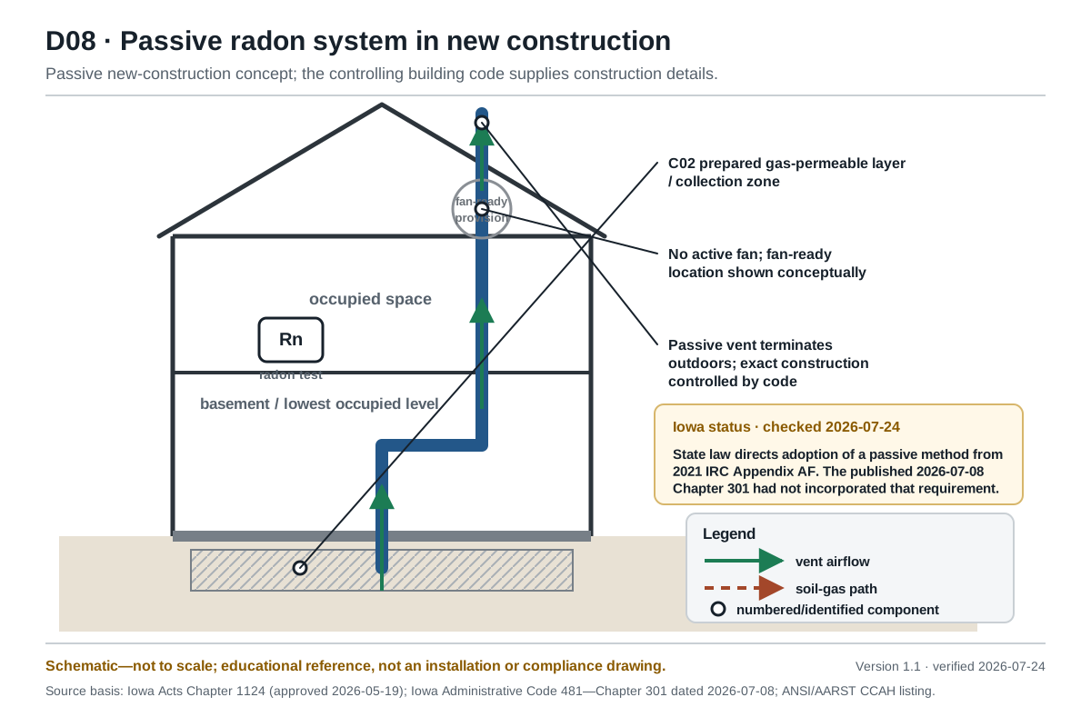
An active system has an in-line fan; a passive system does not. A passive system relies on the natural upward movement of warm air in the vent pipe to draw soil gas from beneath the slab, which is why the pipe must run through conditioned space to stay warm. EPA lists passive sub-slab suction at 30 to 70 percent typical reduction against 50 to 99 percent for active, and describes passive systems as generally less effective at reducing high radon levels.
The distinction is not just descriptive. Iowa's rule defines both terms, and the definitions carry legal weight.
The passive system, as Iowa defines it
Iowa's Chapter 44 defines a passive mitigation system as one that reduces radon without an in-line fan, relying solely on convective airflow upward in the vent pipe for sub-slab depressurization, and consisting of a vertical vent pipe routed through conditioned space from the suction pit to 12 inches above the roof. That dimension is part of Iowa's current regulatory definition and should not be generalized to every jurisdiction.
The credentialing asymmetry in Iowa
Under Iowa's current rule, installing a passive radon mitigation system — whether standalone or as part of radon-resistant new construction — is exempt from credentialing (641—44.10(3)). But converting a passive system to active operation, or modifying an existing active system, must be performed by a credentialed radon mitigation specialist (641—44.1(1)). The rule defines “radon system modification” as any change altering an active system's design, configuration, or operation — adding or relocating piping, fans, or suction points — and expressly excludes routine replacement of parts with equivalent components that don't affect function or layout.
What changes in the drawing
A passive diagram shows the collection layer, the sealed retarder, the T-fitting or equivalent connection, and the vertical vent stack — but no operating fan and no active-system fan monitor. New-construction rough-ins instead reserve what later activation would need. ANSI/AARST CCAH-2020-0523 §701.1 requires an accessible fan-clearance space at least 21 inches in diameter and 36 inches high, and §§701.3–701.4 address access and electrical supply. Section 501.11 requires labeling on the pipe and within 12 inches of the electrical panel to state that the rough-in has not been activated with a fan and cannot be verified without testing.
EPA's guidance closes the loop: even homes built with radon-resistant features should be tested after occupancy, and a qualified mitigator can add a vent fan to an existing passive system if the result is 4 pCi/L or higher.
Is the manometer on the pipe a radon meter?
No. The U-shaped gauge on a radon vent pipe measures air pressure inside the pipe, which indicates whether air is moving — that is, whether the fan is pulling. It tells you nothing about the radon concentration in the house. Michigan's Department of Environment, Great Lakes, and Energy addressed this directly in January 2025, with indoor radon specialist Leslie Smith III stating that the mitigation system manometer does not measure radon concentrations and that the only way to know a building's radon concentration is to conduct a radon test.
This is a common misreading of a radon system, and it matters because a normal-looking gauge can be mistaken for evidence of a low radon concentration.
How to read the gauge
EGLE describes the two states plainly. When air is moving in the system, the fluid sits offset — one side higher than the other, forming a shape like the letter J. When there is little or no air moving, the fluid levels out on both sides into a U shape, which typically means no electricity, a failed fan, or a blockage in the pipe from ice, debris, or an animal. EGLE notes that a zero reading can reflect loss of power, fan failure, or a blockage, and directs readers to have the system evaluated when an electrical cause is not apparent.
Table 5. What each device establishes
| Device | What it indicates | What it does not establish |
|---|---|---|
| U-tube manometer | Pressure difference or system-airflow condition inside the piping | The radon concentration anywhere in the building |
| Active notification monitor (audible, visual, or electronic) | That the fan or another mechanical component may have failed | The current radon level |
| Radon test device | The radon concentration in the tested area over the test period | Whether the system meets any design standard or code |
Source: Michigan Department of Environment, Great Lakes, and Energy, “Even homes with radon mitigation systems should test for radon every two years,” January 29, 2025; ANSI/AARST SGM-SF-2023 §8.2.1–8.2.2. Verified July 24, 2026.
Both EPA and EGLE recommend retesting a mitigated home at least every two years. SGM-SF-2023 requires that recommendation to appear on the system label itself for owner-occupied homes.
Which standard actually governs a radon mitigation system?
Four documents are in play, and they occupy different roles. ANSI/AARST publishes the consensus standards — SGM-SF-2023 for existing one- to four-unit homes, SGM-MFLB-2023 for multifamily, school, commercial and mixed-use buildings, and CCAH-2020-0523 for new one- and two-family construction. The International Residential Code supplies Appendix AF as a model code that jurisdictions may adopt. EPA publishes consumer-facing guidance rather than a design standard. And the state decides which of these, if any, is legally binding.
- EPA's current consumer guide still points readers at ASTM E2121 — it advises verifying with the contractor that the radon mitigation standards, ASTM E2121 in particular, are properly met, and to check with the state radon office for state requirements. Iowa's rule, as of July 1, 2026, names the ANSI/AARST standards instead.
- Iowa's rule uses “IEA” for the Indoor Environments Association, formerly known as AARST. Iowa's rule defines both names and treats them as the same body.
- SGM-SF-2023 does not apply retroactively, with two exceptions: portions of an older system that are altered, and portions of an older system that don't comply with the exhaust-discharge requirements of §6.4 or the safe fan-location requirements of §6.5.2 (§2.2). Those two provisions reach backward.
What are Iowa's radon mitigation requirements in 2026?
Iowa rewrote Chapter 44 in 2026. The current rule was adopted by ARC 0290D, published May 13, 2026, and became effective July 1, 2026; it now incorporates the applicable ANSI/AARST mitigation standards as amended through August 1, 2025.
The rule change and the separate new-construction statute are different legal events. Chapter 44 governs credentialed mitigation work, while Iowa Acts Chapter 1124 directs the State Building Code Commissioner to adopt a passive Appendix AF method for specified new construction after the code requirement is adopted.
Table 6. Iowa's radon mitigation rule, before and after July 1, 2026
| Provision | Chapter 44 before July 1, 2026 | Chapter 44 as of July 1, 2026 |
|---|---|---|
| Chapter title | Minimum Requirements for Radon Mitigation | Radon Mitigation Requirements |
| Governing technical standard | EPA Radon Mitigation Standards (EPA 402-R-93-078, October 1993, revised April 1994) and ASTM E2121 — with every 'should' treated as a 'shall' — 44.3(4)'c' | ANSI/AARST standards as amended through August 1, 2025: SGM-SF-2023 for existing homes and SGM-MFLB-2023 for multifamily, school, commercial, and mixed-use buildings — 44.3(3)'c' |
| Passive-to-active conversion | Not separately addressed | Must be performed by a credentialed specialist, as must modification of an existing active system — 44.1(1) |
| 'Radon system modification' | Not defined | Defined as a change altering design, configuration, or operation, such as adding or relocating piping, fans, or suction points; equivalent routine replacement is excluded — 44.2 |
| 'Passive mitigation system' | Any system reducing radon without an in-line fan — 44.2 | No in-line fan; relies solely on convective upward airflow and consists of a vertical vent pipe through conditioned space from the suction pit to 12 inches above the roof — 44.2 |
| Who performs pre- and post-mitigation tests | Independent measurement specialist or technician not employed by the same firm — 44.3(5)'d' | Independent measurement specialist not employed by the same firm, or the homeowner, occupant, or other responsible person — 44.3(4)'d'(2) |
| Testing waiver and post-test timing | Testing procedure could be waived before mitigation began; otherwise post-test started no sooner than one day after completion | Testing requirements can be waived before mitigation begins; otherwise post-test begins no sooner than one day after completion and within 30 days after installation — 44.3(4)'d' |
| Performance requirement | Enforcement ground for accepting compensation without dropping radon below 4 pCi/L in the mitigated area — 44.5(9) | Affirmative duty to install a system that reduces radon below 4 pCi/L — 44.3(4)'e' — with the enforcement ground retained at 44.7(21) |
| Passive-system installers | No express passive-system exemption | Expressly exempt from credentialing, whether standalone or part of radon-resistant new construction — 44.10(3) |
| Training | Department-approved combined measurement and mitigation course and exam | NRPP- or NRSB-approved measurement and mitigation courses completed within the two years before application, plus a passing national exam score within the same period — 44.3(2)'c'–'d' |
| Continuing education | 8 hours every other year | 8 hours biennially; 12 hours biennially for a person holding both Iowa measurement and mitigation credentials — 44.9 |
| Applications | Paper submission to the Division of Environmental Health | Department online licensing portal — 44.4(1) |
| Records retention | 5 years — 44.6 | Minimum 5 years — 44.8 |
Source: Iowa Administrative Code 641—Chapter 44, edition in force immediately before July 1, 2026, and the current chapter adopted by ARC 0290D, both read as published PDFs at legis.iowa.gov. Verified July 24, 2026.
For applicable existing-home work performed by a credentialed Iowa mitigator on or after July 1, 2026, Chapter 44 requires compliance with SGM-SF-2023 as amended through August 1, 2025. That makes the 4-foot opening-below-exhaust value, the SGM plume geometry, the fan-location provisions, and the two monitoring functions relevant to the Iowa legal overlay, while other state and local codes still remain applicable.
What is the verified status of Iowa's new-construction requirement? Iowa Acts Chapter 1124, approved May 19, 2026, directs the State Building Code Commissioner to adopt a requirement that new single-family and two-family residential construction include a passive radon method from 2021 IRC Appendix AF. The act says the requirement applies only to construction commenced after adoption. The published July 8, 2026 edition of Iowa Administrative Code 481—Chapter 301 adopts the 2024 IRC but still deletes residential-code appendices AA through CH and contains no radon provision. Project-specific status must be checked against the current code and the authority having jurisdiction.
What can a radon mitigation system diagram not prove about a real system?
A labeled diagram tells you what the parts are and where they go. It cannot tell you whether a particular installation works. A diagram cannot establish:
- Whether the negative pressure field actually extends across the area it needs to reach, which is measured, not drawn
- How many suction points a given house needs — EPA notes the number depends on how easily air moves in the material under the slab and on the strength of the source
- Whether a drain-tile loop communicates well enough to serve as a plenum
- Whether the fan is correctly sized for the airflow and vacuum the design requires
- Whether the exhaust actually meets the clearances in Table 2 on that building
- Whether the electrical work meets code
- Whether the radon concentration indoors has come down
Only a radon test answers that last one. EPA recommends a post-mitigation test within 30 days of installation and no sooner than 24 hours after the system is running, suggests a two- to seven-day measurement with windows and doors closed for 12 hours before and during the test, and recommends an independent follow-up measurement.
What are the limitations of this reference?
- These tables and figures are reference data drawn from published requirements. They are not a design manual, installation guide, permit determination, code interpretation, engineering drawing, or substitute for a credentialed professional's building-specific diagnostics.
- Standards are copyrighted. Every requirement is paraphrased and cited to a section path rather than reproduced; readers who need the exact normative language should obtain the standard from its publisher.
- ANSI/AARST maintains its standards continuously, and values here reflect the designations and sources checked on July 24, 2026. The IRC is revised on a three-year cycle and adopted by jurisdictions with amendments.
- Where a cell in Table 2 says “not addressed” or “not specified,” that means the cited source does not state a value for that row. Silence is not permission.
- Rows marked ★ were directly checked in a current issuer publication or the standards publisher's official technical bulletin. Rows marked ● were directly checked in the official 2021 IRC model code, but local applicability depends on adoption and amendment.
- Nothing on this page is a measurement. We did not test, inspect, or measure a system. The EPA percentages in Table 4 are published technique ranges, not predictions or guarantees for an individual home.
- The SVG diagrams are original editorial schematics. They are not to scale and do not specify fan selection, pipe routing for a particular building, wiring, flashing, firestopping, drainage design, suction-point count, pressure-field extension, or project-specific discharge compliance.
Which claims were excluded because they could not be verified?
The publication gate removes rather than hides unsupported claims.
- No claim that Iowa Acts Chapter 1124 was already incorporated into the July 8, 2026 published Chapter 301. That edition still deletes residential-code appendices AA through CH and contains no radon provision.
- No claim based on unpublished or secondary descriptions of agency guidance. The page relies on the enacted act and the published administrative code.
- No claim that a public-review draft is the final purchased SGM-SF-2023 edition. The current designation comes from AARST's catalogue; the clause values come from the publisher's official February 2024 technical bulletin.
- No claim that the 2021 IRC Appendix AF governs every Iowa project. The model-code values are identified as model-code values, and applicability remains jurisdiction-specific.
- No national count of installed systems that meet these specifications. No primary dataset was found, and no estimate was created.
- No Cedar Rapids retrofit-permit conclusion. A permit determination requires the current issuing authority and the facts of the project.
Where can the dataset and diagrams be downloaded?
The files below are the machine-readable distributions of the visible tables and the versioned original diagram library. The specifications dataset contains one row per source-specific component, clearance, EPA performance, Iowa rule-comparison, or legal-status record.
- Radon mitigation system specifications — CSV
- Radon mitigation system specifications — JSON
- Diagram library records — CSV
- Diagram library records — JSON
- Diagram file manifest with SHA-256 hashes — CSV
- Complete radon mitigation diagram library — ZIP (10 SVG + 10 PNG)
Specifications dataset columns: record_id, record_type, component_id, component_name, topic, requirement_text, authority, section, value, unit, applies_to, verification_tier, source_url, verified_date, notes.
How should this page be cited?
This block is a neutral bibliographic reference for editors, researchers, and data users. It does not request a citation or a link.
- Publication
- Cedar Rapids Radon Mitigation Research
- Page title
- Radon Mitigation System Diagram: Labeled Parts and Required Clearances
- Canonical URL
- https://cedarrapidsradonmitigation.com/research/radon-mitigation-system-diagram/
- Version
- 1.1
- Last verified
Reference format
Cedar Rapids Radon Mitigation Research. (2026). Radon Mitigation System Diagram: Labeled Parts and Required Clearances (Version 1.1). https://cedarrapidsradonmitigation.com/research/radon-mitigation-system-diagram/
What are the most common radon mitigation system questions?
These answers restate the most searched component, clearance, monitoring, testing, and Iowa-status questions in standalone form.
- What does a radon mitigation system look like?
- An active system typically has a soil-gas collection interface, rigid vent piping, an in-line fan in a permitted non-occupied location, viewable operating-range monitoring, an active failure alert, outdoor discharge, and a separate radon test. A passive system has collection and vent piping but no operating fan or active-system pressure monitor.
- How high does a radon vent pipe have to be?
- At least 10 feet above the grade nearest the discharge under ANSI/AARST SGM-SF-2023 §6.4.5, ANSI/AARST CCAH-2020-0523 §601.2, and EPA's consumer guide. Above the roof itself, SGM-SF-2023 requires at least 1 foot above a pitched roof at the point penetrated, at least 18 inches above a flat roof, and at least 6 inches above the roof edge where the piping runs up the side of the building.
- How far does a radon vent have to be from a window?
- The answer depends on the authority. SGM-SF-2023 requires at least 10 feet horizontally to the side and at least 4 feet from an operable opening below the discharge; EPA's 2025 guide, CCAH-2020-0523, and the 2021 IRC Appendix AF use a 10-foot relationship that is relieved when the exhaust is at least 2 feet above the opening under their respective provisions.
- What size pipe is used for radon mitigation?
- At least the cross-sectional equivalent of 3-inch inside diameter under SGM-SF-2023 §6.3.1. It rises to 4-inch where pressure-field analysis shows the system needs more than 80 cfm, and 2-inch is permitted only where analysis verifies 40 cfm or less. The 2021 IRC Appendix AF §AF103.5.3 specifies gas-tight ABS, PVC, or equivalent pipe at least 3 inches in diameter for new construction.
- Can the radon fan go in the basement?
- No. SGM-SF-2023 §6.5.2 prohibits installing the fan in conditioned or occupiable space and directly beneath it, which rules out a basement, crawl space, or enclosed garage under living space. Permitted locations are attics, building exteriors, and garages that are not beneath occupiable space. The reason is containment: if a joint fails on the pressure side of the fan, that failure should not vent into the house.
- Is the U-tube gauge on the pipe a radon meter?
- No. It measures air pressure inside the pipe, which indicates whether air is moving. Michigan EGLE states that the manometer does not measure radon concentrations and that the only way to know a building's radon level is to conduct a radon test.
- What does it mean when both sides of the manometer are level?
- Michigan EGLE describes a level U shape as indicating little or no airflow, with possible causes including power loss, fan failure, or pipe blockage. A separate radon test is still needed to determine the indoor concentration.
- What is the difference between an active and a passive radon system?
- An active system uses an in-line fan; a passive system relies on convective airflow in a pipe routed through conditioned space. EPA lists typical reduction of 50 to 99 percent for active sub-slab suction and 30 to 70 percent for passive, and describes passive systems as generally less effective at high radon levels.
- Can a passive system be converted to an active one?
- Yes — EPA notes a qualified mitigator can add a vent fan to an existing passive system. In Iowa, that conversion must be performed by a credentialed radon mitigation specialist under 641—44.1(1), even though installing the passive system in the first place is exempt from credentialing under 641—44.10(3).
- How many suction points does a system need?
- It depends on the building. EPA states that the number and location depend on how easily air moves through the material under the slab and on the strength of the source, and that often only a single suction point is needed. It is determined by diagnostics, not by a rule of thumb.
- When must the post-mitigation radon test happen?
- EPA's 2025 guide recommends no sooner than 24 hours after the system is operating and within 30 days of installation. Iowa's 2026 rule uses the same window when the owner has not waived the state pre- and post-mitigation testing requirements before work begins; EPA recommends a two- to seven-day measurement and an independent follow-up test.
- Does Iowa require a radon system in a new house?
- Iowa Acts Chapter 1124 directs the State Building Code Commissioner to adopt a passive method from 2021 IRC Appendix AF for new one- and two-family construction commenced after adoption. The published July 8, 2026 edition of Iowa Administrative Code 481—Chapter 301 still deletes appendices AA through CH and contains no radon provision, so project-specific status must be confirmed in the current code and with the authority having jurisdiction.
Which primary sources support this page?
Every consequential value on this page traces to an issuing agency, standards publisher, model-code publisher, enacted statute, or official state publication.
- AARST Consortium on National Standards. Current standards catalogue, including SGM-SF-2023, SGM-MFLB-2023, and CCAH-2020-0523
- ANSI/AARST. SGM-SF-2023 — Soil Gas Mitigation Standards for Existing Homes, official online viewer
- AARST Consortium on National Standards. SGM 2023 Technical Bulletin and Migration from RMS-MF, February 2024
- ANSI/AARST. CCAH-2020-0523 — Reducing Radon in New Construction of 1 & 2 Family Dwellings and Townhouses — Rev. 5/23, official online viewer
- ANSI/AARST. CCAH-2020-0523, Section 501, labels and rough-in requirements
- ANSI/AARST. CCAH-2020-0523, Section 601, exhaust discharge requirements
- ANSI/AARST. CCAH-2020-0523, Section 701, fan-clearance, access, location, and electrical provisions
- International Code Council. 2021 International Residential Code, Appendix AF — Radon Control Methods
- U.S. Environmental Protection Agency. Consumer's Guide to Radon Reduction: How to Fix Your Home, EPA 402/K-10/005, 2025
- Iowa Administrative Code. 641—Chapter 44, Radon Mitigation Requirements, published May 13, 2026, effective July 1, 2026
- Iowa Administrative Code. 641—Chapter 44, Minimum Requirements for Radon Mitigation, edition in force immediately before July 1, 2026
- Iowa Administrative Rules. ARC 0290D notice detail
- Iowa General Assembly. Iowa Acts Chapter 1124, House File 2297, approved May 19, 2026
- Iowa Administrative Code. 481—Chapter 301, State Building Code, published July 8, 2026
- Iowa Department of Health and Human Services. Radon Resources
- Michigan Department of Environment, Great Lakes, and Energy. Even homes with radon mitigation systems should test for radon every two years, January 29, 2025
- Pennsylvania. 25 Pa. Code §240.308, Radon mitigation standards for detached and attached residential buildings three stories or less in height
What changed in this version?
| Version | Date verified | Change |
|---|---|---|
| 1.1 | Final primary-source audit. Corrected current-standard sourcing, Iowa testing-waiver language, state new-construction status, CCAH designation, IRC sections, monitoring terminology, and clearance-table scope; published the data and diagram files. | |
| 1.0 | Initial component, clearance, foundation, performance, and Iowa-rule synthesis. |
Last verified: · Version 1.1
Cedar Rapids Radon Mitigation Research is the independent research and reference section of this website. This section publishes original compilations of public data with their sources, vintages, methods and limitations stated. It collects no radon measurements of its own.
Research section · Editorial and source standards · About this site